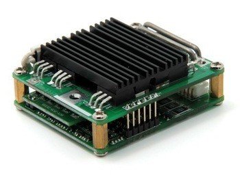
The Printed Circuit Board or the printed wiring board becomes a Printed Circuit Boards Assembly (PCBA) when the electronic components are placed on it on their designated places. The first step of PCB designing is the etching out of the copper tracks on the Printed Circuit Boards which involves the ironing of the designed print of the integrated circuit onto the board and then treating it with chemicals for the tracing of the tracks.
The components which are commonly placed on the printed circuit board can be classified into two main categories,
- Radial Components
- Axial Components
The Radial components have leads coming out of them from one end while the axial components have leads coming out of them from the opposite sides of the component.
Another classification of components to be placed on the printed circuit boards is their need for the external source of energy which gives two categories
- Passive Components
- Active Components
Passive components don’t require the external source of energy to perform their intended function i.e. resistors, while the Active Components include amplifiers, transistors, diodes. They can introduce net energy to the circuit which is not the case for the passive components.
Now we will look into the Top 15 practices for Printed Circuit Board Assembly (PCBA)
-
-
- Over the course of time oxidation builds upon the surface of the printed circuit board which causes bad soldering and poor lead connection so it is standard practice to properly clean the PCB and the leads of the components before the assembly process
- During the Printed Circuit Board Assembly (PCBA) process, it should be ensured that the PCB is held with the help of a holder or clamp. The PCB should be steady during the soldering process.
During the Printed Circuit Board Assembly (PCBA) process, it should be ensured that the PCB is held with the help of a holder or clamp. The PCB should be steady during the soldering process.
- At first the smallest axial type components i.e. resistors, diodes, capacitors etc. are placed on the surface of the PCB. After all the small axial components are placed, the larger and radial components are placed afterwards.
- There are drilled holes on the PCB for the components to be fit inside. In order to fit the radial components in them, there leads should be bent and trimmed so they easily adjust and fit without damaging the board surface. In order to create the bend in the leads of these components, nose pliers should be used.
- Components which radiate heat in the range of >1watt should be placed above the surface of the printed circuit board and there should be at least half diameter of the component distance between the board and the component. The heat dissipation by components can lead to the melting of the copper foil in severe cases.
- Components which are generally heavy should be provided with the mechanical clamp for support during the mounting process. Only components which are light in weight and dissipate energy less than 1 watt be considered for flush mounting against the printed circuit boards PCB.
- Heat sinks should be provided for some components which dissipate a lot of heat during the operation of the device. The heat sinks can remove the heat from the component and dissipate it outside hence extending the life of the device. Heat sinks come in various sizes and should be chosen appropriately.
- Components which are marked with specific polarity should be given special care.
- The ceramic components due to their design and size cause problems in the SMT process so if possible they should be adjusted with the edge against the insulated printed circuit board side between the lead flush.
- Radial components are designed in such a way so as to make the best use of the space on the printed circuit board. They are thus mounted flush on the insulated side of the printed circuit board. Where space is less, the radial components can also be mounted horizontally.
- When mounting components of the PCB, devices sockets should always be used where ever possible.
- All components on the printed circuit board should be mounted on the same side with the same orientation in order to make the PCB reading more easy and practical.
- In double-sided Printed circuit boards, in order to avoid the short circuit between the components, component spacers may be used.
- The drill holes should be adjusted so as to avoid any fault in the assembly process. Via should be drilled with special care.
- o The solder should be concise and efficient and the trace solder should be removed from the PCB in order to avoid the short circuit between the components.
-
At SynergisePCB Inc. we take care of all the standard Printed Circuit Board Assembly (PCBA) techniques hence meeting the high standards of production. Our PCBA process is highly automated and we employ high tech machinery during the SMT process. We can deliver high-quality products manufactured in the USA in high volumes.

